|
|
||
|---|---|---|
| hwids | ||
| images | ||
| include | ||
| lib | ||
| src | ||
| test | ||
| .clang-format | ||
| .gitignore | ||
| CMakeLists.txt | ||
| code-format.sh | ||
| license.md | ||
| platformio.ini | ||
| readme.md | ||
| sdkconfig.defaults | ||
readme.md
OpenRetroPad
Adapt various input devices to various output devices.
Currently supported inputs: SNES/NES, Sega Genesis/Megadrive/Atari, Sega Saturn, Playstation (and PS2) Digital and Dual shock, Nintendo 64, Nintendo Gamecube, Nintendo Wii Nunchuck/Wii Classic/SNES+NES Mini
Currently supported outputs: bluetooth-hid gamepad, usb-hid gamepad, nintendo switch usb gamepad, wireless usb-hid gamepad over radio
OpenRetroPad is written and tested on an Arduino Pro Micro and an ESP32, there is also an in-progress custom PCB being developed at OpenRetroPadHW
Build using PlatformIO using pio run or pio run -e $board-$input-$output for a specific target/env.
env's are laid out like $board-$input-$output
supported values:
- $board: micro, esp32
- $input: snes, genesis, saturn, psx, n64, gc, wii, radio, debug
- $output: radio, usb, usbradio, switchusb, bt, debug
- please note not all boards are compatible with all inputs/outputs, for example esp32 can only do bt, micro can only do radio or usb
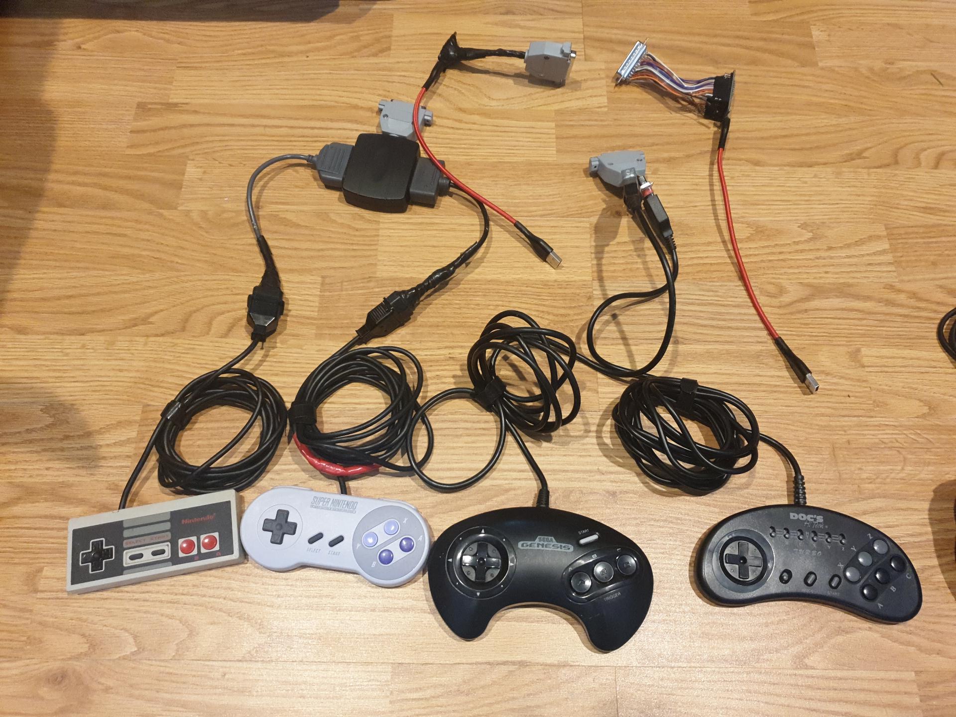
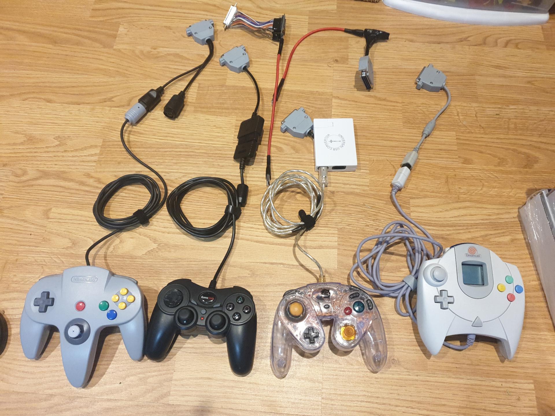
Pics
My controllers and adapters I used to build+test this (and play with, of course!)
Wiring
(quick plea: if you are good at drawing diagrams, please help!)
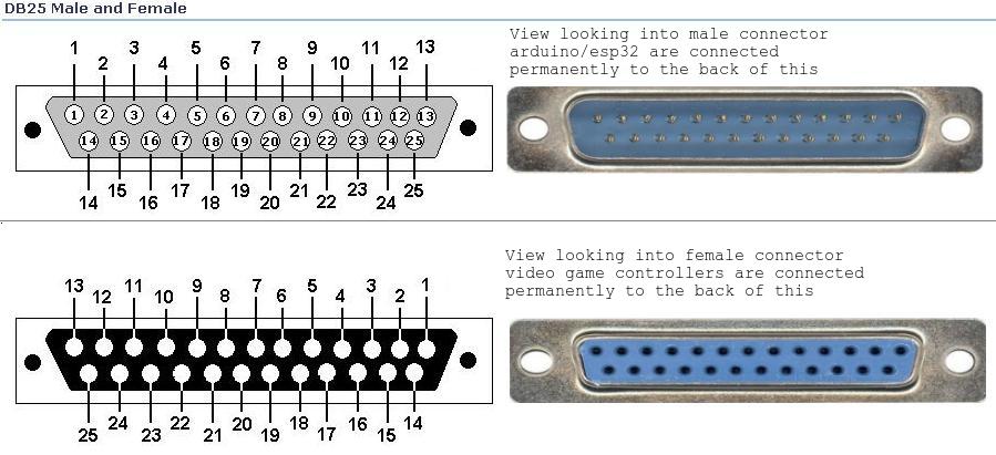
| DB-25 Pins | Arduino Pro Micro GPIO | ESP32 GPIO | Radio | SNES | PSX | N64 | Gamecube | Genesis | Dreamcast | Saturn | Wii Ext |
|---|---|---|---|---|---|---|---|---|---|---|---|
| 1 TX | 1 | 19 | - | LATCH | - | - | - | P1-1 | P1-DATA1 | P1-7 | - |
| 2 SDA | 2 | 21 | - | CLOCK | DATA | P1-DATA | P1-DATA | P1-3 | P1-DATA5 | P1-2 | SDA |
| 3 SCL | 3 | 22 | - | P1-DATA | CMD | - | - | P1-4 | - | P1-3 | SCL |
| 4 Analog | 4 | 15 | - | P2-DATA | ATT | - | - | P1-6 | - | P1-6 | - |
| 5 Digital | 5 | 16 | - | P3-DATA | CLK | - | - | P1-7 | - | PX-5 | - |
| 6 Analog | 6 | 2 | - | P4-DATA | - | - | - | P1-9 | - | PX-4 | - |
| 7 Digital | 7 | 17 | CE | - | - | - | - | P2-7* | - | - | - |
| 8 Analog | 8 | 4 | CSN | - | - | - | - | - | - | - | - |
| 9 Analog | 9 > 1k Ω | 35 > 1k Ω | - | 330 Ω | 100 Ω | 220 Ω | 680 Ω | 470 Ω | 820 Ω | 1000 Ω | 1500 Ω |
| 10 Analog | 10 | 32 | - | - | - | - | - | - | - | P2-6 | - |
| 11 RX | 0 | 18 | - | - | - | - | - | P1-2 | - | P1-8 | - |
| 12 - | - | - | - | - | - | - | - | - | - | - | - |
| 13 - | - | - | - | - | - | - | - | - | - | - | - |
| 14 MISO | 14 | 12 | MISO | - | - | - | - | P2-6* | - | - | - |
| 15 SCLK | 15 | 14 | SCLK | - | - | - | - | P2-9* | - | - | - |
| 16 MOSI | 16 | 13 | MOSI | - | - | - | - | - | - | - | - |
| 17 - | - | - | - | - | - | - | - | - | - | - | - |
| 18 Analog | 18 | 27 | - | - | - | - | - | P2-1 | - | P2-7 | - |
| 19 Analog | 19 | 26 | - | - | - | - | - | P2-2 | - | P2-8 | - |
| 20 Analog | 20 | 25 | - | - | - | - | - | P2-3 | - | P2-2 | - |
| 21 Analog | 21 | 33 | - | - | - | - | - | P2-4 | - | P2-3 | - |
| 22 - | - | - | - | - | - | - | - | - | - | - | SENSE |
| 23 3.3V VCC | - | 3.3V VCC | 3.3V VCC | - | - | 3.3V VCC | 3.3V VCC | - | - | - | 3.3V VCC |
| 24 5V VCC | 5V VCC OUT | 5V VCC | 5V VCC | 5V VCC | 5V VCC | - | 5V VCC | PX-5 5V VCC | 5V VCC | PX-1 5V VCC | - |
| 25 GND | GND | GND | GND | GND | - | GND | GND | PX-8 GND | GND | PX-9 GND | GND |
- 2nd player Genesis is incompatible with Radio because it uses the same pins, 1 player Genesis is compatible
Ω This is optional and only used for dongle detection. On the microcontroller side, put a 1k resistor between DB-25 pin 9 and VCC (3.3v for ESP32, 5V for Micro). On each controller dongle, put a resistor of the given value between DB-25 pin 9 and GND.
All connected pins can also function as Digital pins.
Credits / Links
Code and/or inspiration was (or will be) taken from these places, in no particular order: